PCB Motor

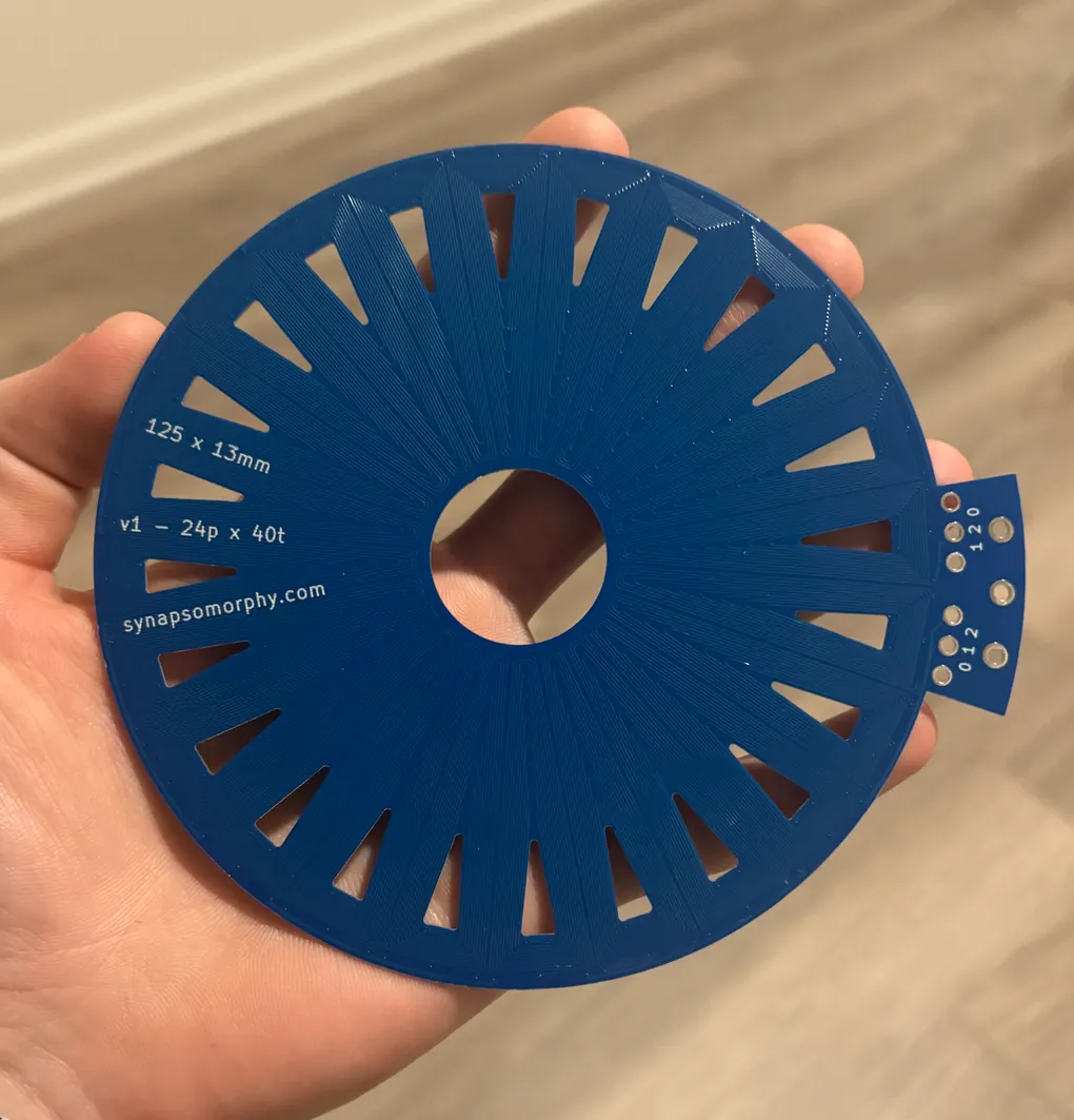
Inspired by Carl Bugeja and atomic14’s videos, I designed and built an axial flux 3 phase brushless DC motor where the stator is a PCB with the coils built into it. No winding needed!

I used a Python script to generate the Kicad file. The only part not generated by the script is the interconnects from the terminals on the right to the phases, which takes maybe 30 seconds. Everything else can be changed just by changing the values in the script - number of layers, number of coils, trace width, number of turns, etc.
I designed the PCB to be stacked. Stacking directly (without rotating) puts the phases of the PCBs in parallel, doubling the current capacity. Stacking while rotating one PCB by the angle of one coil, in this case 15deg (360deg/24 coils - note how the phase terminals are rotated by this angle) puts the phases in series, doubling the turns and increasing the inductance. Having the ends of each phase exposed also lets you do some neat stuff like easily change between delta and Y winding types. This stackable design is the main innovation in this project.
This design mitigates the glaring issue with PCB stators: there’s just not that much copper. Well, there still isn’t that much copper, but there can be more when you can keep stacking PCBs. I paid a bit extra to make them pretty thin (0.8mm) and to increase the copper thickness on all layers (2oz). The total cost was $150 for 10, so 15 per board, with a huge chunk of that being for the increased copper thickness (combined with the thin board). This puts the total copper by volume at around 20% (this is calculated using the known trace width, trace spacing, and calculated copper thickness).
After receiving the PCBs, I could measure the phase resistance, which is about 20 ohms. I calculated it to be around 40 ohms. So that’s nice, but I’m really not sure where the discrepancy comes from. For designing future motors I’d really like to know why I was so far off so this is something I’ll be investigating.
20 ohms means I can push around 1A through 1 PCB at 24V, or around 5A by stacking 4 in parallel.

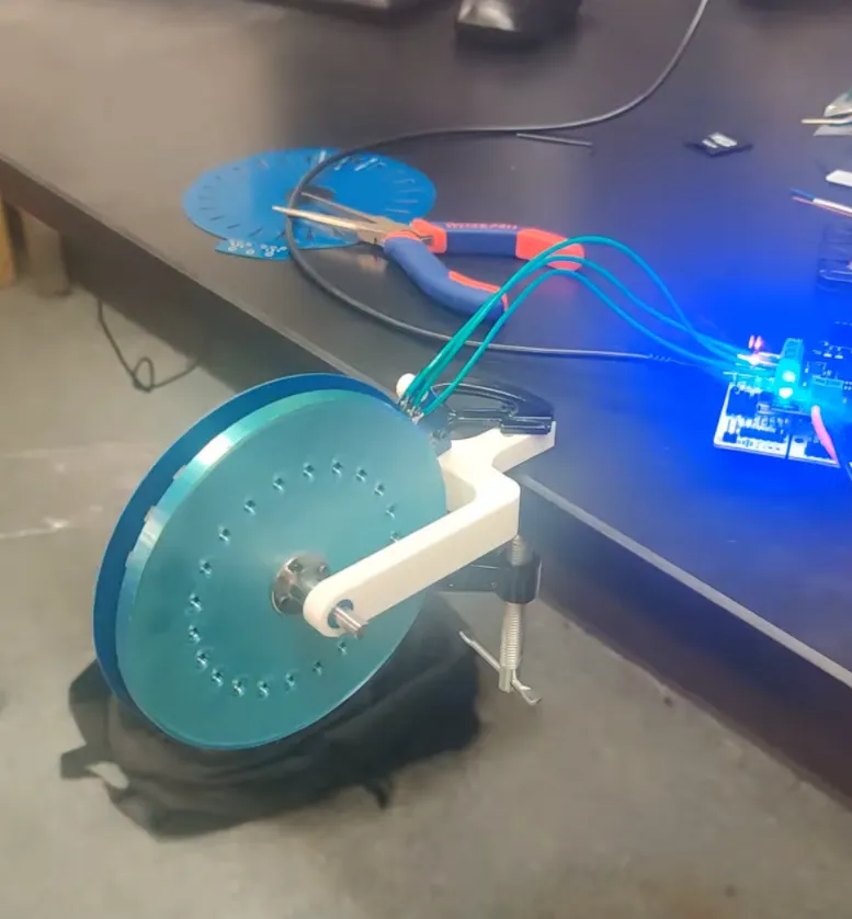
Above is the assembled motor. I printed out a holder (white) that bearings press fit into, and a rotor (blue) that magnets press fit into, and that has holes for a flange coupler to bolt onto. I left holes on the back of the rotor to push the magnets back out if I wanted to change designs or to reorient them which ended up being a very smart decision.
I’m driving the motor using an STM32 dev board with a simpleFOC hat. This project was largely inspired by wanting to fiddle with simpleFOC because it’s such a cool project and community.
I’m still working on testing the motor, but initial results are.. not good! It just kinda wobbles. I initially tried 1 board, then stacked 4, and it definitely does have 4x the current and movement ability with the stacked setup. I haven’t tried stacking in series yet - the boards I ordered already have a lot of turns (10 turns per layer x 4 layers = 40 per coil), maybe too many. I think the alignment between the stator and rotor might need to be a lot better. I also have yet to try closed loop mode (where a diametrically magnetized magnet sits on the end of the shaft, which lets an encoder measure the motor’s position). I think that might improve things a lot.