Self Stabilizing Stick

This project is a subset of the Hopper project, more on that here. I built this in September 2022. The purpose of this project was to get more experience with control systems.
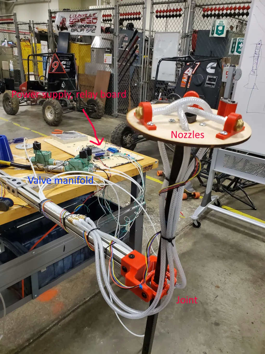
I designed, built, programmed, and tuned all parts of this stick. It consists of a carbon fiber rod held in a joint, free to swivel. Attached to the rod is an IMU (BNO055) and compressed air nozzles (using shop compressed air) controlled by solenoid valves (manifold visible in picture below). A Raspberry Pi talks to the IMU and the solenoid valves (by way of a relay board) and runs control code.
The “nozzles” are just cap fittings with a hole drilled in them. They are secured to the stick by 3D printed brackets which are bolted to a laser-cut wood circle, which is then attached to the rod with another 3D printed bracket. The rod is clamped at the joint, instead of bolted, to allow for easy adjustment. The joint has four bearings, which lets the rod swivel smoothly on two axes. The joint is attached to 80/20 extrusion, which extends to a table where it is weighted down to keep everything upright. The rod also features attachment points to add mass, which is important to change the rod’s moment of inertia and thus its control characteristics. Changing MoI is the purpose of the large metal objects above and below the joint.
The solenoid valves are meant for use in irrigation (I chose them because of their very low cost), which somewhat limited the final control abilities of the stick: the minimum time the valves would stay open for was around a quarter second, and within that constraint the stabilization displayed in the video above is about as good as it got working, unless we ever swap in new valves (they are the bottleneck control-wise of the system).
The part of this project where I learned the most was the control code. I’d never done custom closed-loop control before, and in this project I programmed a PD loop (proportional + derivative) from the ground up in Python, without using any control libraries. If I redid this project, I would instead choose C because it is much more common for this type of application and it runs much faster. Python’s speed wasn’t a limitation in this case because the valves were so slow, but it’s just not really meant for this kind of application.
The IMU worked for this application, but not perfectly. The BNO055 is 9DOF (accel + gyro + mag), but I mainly just used the accelerometers. It did have some issues with forgetting settings and resetting sensor calibration, which I solved by just feeding it all of that information every few seconds. It also had a strange intermittent issue where two of it axes flipped with no discernible cause, obviously destroying the ability of the system to control itself. If I were to redo this project, I would probably choose a simpler IMU- some of the sensor fusion modes caused issues, and I didn’t really need the 9DOF capability.
All of my prints pretty much worked on the first try. I did have to reprint the part of the joint that interfaces with the aluminum extrusion because it was too small. The nozzles also worked well enough. It was possible to turn the compressed air wall valve and meter how much air came out, which helped with finding the sweet spot for good control. The tubing I initially chose was too flexible and would balloon a concerning amount with compressed air inside (the 100psi of the wall was way more than it was rated for), so I swapped it for more rigid, thicker-walled tubing which worked well but yanked on the rod more, which made control a bit tougher.
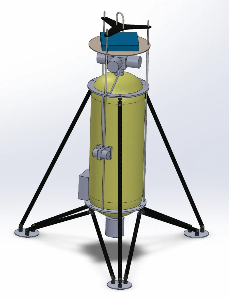
This stick imitated the control setup of our planned vehicle, pictured below, with cold gas (CO2) nozzles on top of the vehicle for attitude control.

There’s many projects I’d like to do in the future that involve controls in some way, and this project was a great way to get my feet wet with them and learn the basics.